 Index
Index
- Bird Line Sections
- Comparisons
- Contact Information
- Custom Meter Scales
- Customizing MB-1
- Documentation
- Downloads
- Expansion Features
- Evaluating Analog Meters
- Evaluating Couplers
- FAQ
- Features
- Generic Meter and RF current Measurements
- Hardware Diagnostics
- Interfacing your own Analog Meters
- Interfacing your own Couplers
- Multi-Coupler Display Feature
- Prices
- Programming MB-1
- Projects
- Quick Reference Guide - Menus
- Quick Reference Guide - Switches and LEDs
- Recent Site Updates
- Reviews
- Specifications
- Simulator
- Troubleshooting
- Useful Links
- Using Different Couplers
- Utilities
- Videos
Troubleshooting
Troubleshooting - Self-Test Failures
-
The Processor Test is failing.
-
The Front Panel Switch Test is failing.
-
The Panel Meter Test is failing.
-
The Seven Segment Display Test is failing - Internal
7-Segment LEDs.
-
The Seven Segment Display Test is failing - External
7-Segment LEDs.
-
The External Bar Graph test is Failing.
-
The RS-232 Transmit Test is failing.
-
The RS-232 Receive Test is failing.
-
The Front Panel Pot Test is failing.
-
The Coupler Port Test is failing.
Troubleshooting - General
-
When
I power up the meter, it emits a 2 second beep.
Nothing else happens.
-
The
meter is not operating properly.
-
While
calibrating a coupler, when I try to save a
calibration point, I get error message "NO INPUT,
VAL IGNORED".
-
The Bar Graph on the LCD is not displaying anything.
-
The Bar Graph on the LCD is displaying block
characters instead of the vertical line segments.
-
Some of the 7-Segment modules do not always update
at the same rate.
-
The Characters on the External 7-Segment Hi-Visibility Module are not
displaying Properly.
-
What causes the Panel Meter or Bar Graph to turn off?
-
I
am trying to calibrate a Crossneedle Panel Meter on
Port 5, but I do not see the CROSSNEEDLE Scale
Option.
-
I am trying to calibrate an external analog meter,
but I cannot bring the needle in scale even with the
min CCW trim pot setting.
-
I am trying to calibrate an external analog meter,
but I can barely advance the needle even with the
trim pot at its max (CW) position.
-
Why am I getting an error message when I push one of the front panel
buttons?
-
Forward Power is
always reading 0.
-
My meter sometimes displays low power values when no
power is being applied.
-
I am applying a signal on coupler port 1, but I am
seeing measurements displayed when I select other
coupler ports that are not connected.
-
If I place my transceiver into transmit, and sweep the frequency dial
across the full 500 kHz spectrum of one of the Amateur bands, I see
several frequencies within the 500 kHz range where the analog meter
seems to momentarily drop out. Is this a bug?
-
The linearity of the front panel pot seems to have changed. The step
size at the high end (max CW) of the pot travel seems to be
smaller than I recall.
-
I am trying to program the simulation values for one
of the virtual couplers (coupler 5) using the
Coupler Setup. I have the coupler menu displayed on
line 4 of the LCD when I enter Setup, but I am only
able to choose the real coupler numbers (1 - 4).
-
I
plugged an external analog meter into a rear panel
RCA jack on MB-1, and the
meter needle now looks like a pretzel.
- When I power up the meter, it emits a 2 second beep. Nothing else happens.
- The meter is not operating properly.
- While calibrating a coupler, when I try to save a calibration point, I get error message "NO INPUT, VAL IGNORED".
- The Bar Graph on the LCD is not displaying anything.
- The Bar Graph on the LCD is displaying block characters instead of the vertical line segments.
- Some of the 7-Segment modules do not always update at the same rate.
- The Characters on the External 7-Segment Hi-Visibility Module are not displaying Properly.
- What causes the Panel Meter or Bar Graph to turn off?
- I am trying to calibrate a Crossneedle Panel Meter on Port 5, but I do not see the CROSSNEEDLE Scale Option.
- I am trying to calibrate an external analog meter, but I cannot bring the needle in scale even with the min CCW trim pot setting.
- I am trying to calibrate an external analog meter, but I can barely advance the needle even with the trim pot at its max (CW) position.
- Why am I getting an error message when I push one of the front panel buttons?
- Forward Power is always reading 0.
- My meter sometimes displays low power values when no power is being applied.
- I am applying a signal on coupler port 1, but I am seeing measurements displayed when I select other coupler ports that are not connected.
- If I place my transceiver into transmit, and sweep the frequency dial across the full 500 kHz spectrum of one of the Amateur bands, I see several frequencies within the 500 kHz range where the analog meter seems to momentarily drop out. Is this a bug?
- The linearity of the front panel pot seems to have changed. The step size at the high end (max CW) of the pot travel seems to be smaller than I recall.
- I am trying to program the simulation values for one of the virtual couplers (coupler 5) using the Coupler Setup. I have the coupler menu displayed on line 4 of the LCD when I enter Setup, but I am only able to choose the real coupler numbers (1 - 4).
- I plugged an external analog meter into a rear panel RCA jack on MB-1, and the meter needle now looks like a pretzel.
Troubleshooting - Self Test Failures
In the following troubleshooting procedures, always remove power by disconnecting the 12 volt DC power cable before swapping components.
- Q:
The Processor Test is failing.
1. If none of the LEDs on the PIC processor board are lit, check for 5 volt power on the PIC Processor Board. Verify that the white push button on the PIC Processor Board is in the up position and that the jumpers on the PIC Board are in their correct locations as described in the Assembly Manual. The normal state of the LEDs on the PIC board is for one red and one green LED to be lit.
2. If you hear a 2 second beep on power-up, and the rest of the processor tests fail, if you see the Modtronix message on the LCD and it does not change, or if the backlight is not lit in the LCD, check the Processor-to-LCD connectivity as described here.
- 3. If the above steps check OK, check that the LCD
daughter board dip switch settings as described
here.
4. If the above steps check OK, check that the processor SPI bus as described here.
-
Q:
The Front Panel Switch Test is failing.
1. With none of the Front Panel Switches depressed, the LCD message should indicate "NO INPUT SIG DET". If a switch is incorrectly being reported as pressed, check for a ground (0 volts) on one or more of the nine input leads (GPB0 - GPB7, and GPA0) on the I/O Expander chip (MCP-23S17). With no switches depressed, there should be no grounds on any of these pins.
2. If one or more of the switches do not register on the LCD when pushed, confirm that the corresponding switch is applying a ground to the correct input lead of the I/O chip when pressed. If the expected ground is not detected, the problem lies in the related traces on the Switch Board or Controller Board, on on the ribbon cable connection that routes the switch signal to the Controller Board,
3. If the above steps check out OK, check for activity (pulses) on the following pins of the I/O Expander chip (MCP-23S17):
CS, SCK, SI, SO, INTA.
-
Q:
The Panel Meter Test is failing.
Note - If you do not have external meters connected to all four external meter jacks, you can test these ports with a voltmeter. You should see a voltage appear for one second on each of the external analog meter jacks. If you did not install the Expansion Kit components, you will not see any outputs on the external analog meter jacks.
1. If only some of the 6 analog meter outputs are failing to generate a signal and drive the meter needle if connected, check the associated trim pots to make sure they are not at their minimum CCW position.
2. If a signal is missing on only some of the Panel Meter outputs, run the test while measuring the voltage on pin VoutA or VoutB on the MCP-4922 chip associated with the failure. The self test routine drives each output signal to 1/4th the maximum output value (1.25 volts) for one second. If you detect this voltage on the chip, but it is not reaching the RCA jack, there is an open between the chip output and the RCA jack including the path through the trim pot. Trace the path to find the problem.
3. If a signal is missing on just one of the two D-to-A outputs on the MCP-4922 chip, disconnect the 12 volt DC power cable from the meter, remove that MCP-4922 chip from its socket, and use a multimeter to determine if the VoutA or VoutB output that has no output is shorted to ground.
4. If the failure is associated with both outputs of the same D-to-A IC, swap a working MCP4922 with the one that has no output to determine if the problem propagates with the IC. If the ICs are OK, check the power, clock, and chip select pins on the device that is failing.
5. If the failure is associated with all six of the D-to-A outputs, check the power, clock, and chip select leads on all three D-to-A ICs.
-
Q:
The Seven Segment Display Test is failing - Internal
7-Segment LEDs
The self test for the 7-segment displays tests both the internal and external 7-segment LEDs. This section applies if you have a problem with the internal 7-segment LED displays.
1. If none of the internal 7-segment LEDs are lit, check for power on the Display Board, which is supplied from the Controller Board to the Display Board on the JPWR IDC ribbon cable which connects the two boards.
2. If the two left four seven segment modules are operating properly, and the two right modules are not operating properly (or vice versa), check for power on the IC power pins, and for pulse activity on the SPI-OUT, SPI-CLK, and chip select pins on the MAX-7219/Max-7221 LED driver IC associated with the malfunctioning modules. (The driver chip located below each group of LED modules is If the chip that controls those two modules.) If the power and clock signals check out, remove power. Then swap the LED driver chips (MAX 7219/7221) to determine if the problem propagates with the IC.
3. If only one 7-segment digit has a problem, swap that LED with another to determine if the problem propagates with the LED. If not, check the trace(s) between the seven segment driver and the malfunctioning LED.
-
Q:
The Seven Segment Display Test is failing - External
7-Segment LEDs
The self test for the 7-segment displays tests both the internal and external 7-segment LEDs. This section applies if you have a problem with the external 7-segment LED display. - If the external 7-segment is not working and you purchased your MB-1 after 10-8-2012, it is possible that you need make a setting change that is easily accomplished. See the section below on changing the external 7-segment display type to determine if a setting change is required proceeding with detailed troubleshooting below.
-
If you have type C modules, you can temporarily ignore the
results of this test.
After completing the remainder of the self tests,
follow the
procedure below to change the setting to a "C" device. Then
simply repeat the self test to verify that the 7-segment external display works
properly
with the new setting.
-
The following assumes that you are using the 1.5 inch external 7-segment display module that comes with the Expansion Kit. When testing any of the external modules, make sure that you connect the ribbon cable to J1 of the external display module (and not J2). Make sure that the 5 volt power option is selected for both external displays (EXT1 and EXT2) on both of the 3 pin headers on the Controller Board. Applying 12 volts to a 5 volt external display module can destroy it.
The different size external 7-segment display modules use different software drivers. if you are using the 1.5 inch 7-segment module included with the Expansion Kit for this test, make sure to set the driver type (field 4 of the 7-Segment menu for LED module 5 (the external 7-segment display connected to the EXT1 rear panel jack) ) to "A". This is the default value.
1. The Default MB-1 configuration is for one external 7-segment display module (driven from the EXT1 connector on rear panel) and one external bar Graph module (driven from the EXT2 connector on rear panel). If the external 7-segment display does not work properly when plugged into EXT1, temporarily configure MB-1 to drive two external 7-segment displays. To do this, power down the unit. Then press Menu 3 (M3) while powering up the unit.
Using the 7-Segment menu, set field 4 of module 6 to driver type "A". Plug in the external 7-segment module that did not operate properly when connected to EXT1 into EXT2. Both EXT-1 and EXT-2 are now configured to drive external 7-segment displays, and both rear panel connectors will be exercised with the 7-segment test pattern when running the self test.
2. Rerun the self test. If the module that did not work properly when plugged into EXT1 now works when plugged into EXT2 , check the voltages and signals on rear panel connector EXT1.
If the problem persists, check the voltages and signals on both rear panel connectors EXT1 and EXT2. These two connectors share some common signals.
- Q: The
External Bar Graph test is Failing.
When testing any of the external modules, make sure that you connect the ribbon cable to J1 of the external module (and not J2). Make sure that the 5 volt power option is selected for both external displays on both of the 3 pin headers on the Controller Board. Applying 12 volts to a 5 volt module can destroy it.
1. Make sure your MB-1 is configured to operate with one external 7-segment display module and one external Bar Graph module. This is the default configuration.
As a quick check that the meter is configured for External Bar Graph operation, try to select 7-segment module 6 with the Seven Segment menu. If you can select 7-segment module 6, you are configured for two external 7-segment modules and can not exercise the external Bar Graph in this mode. To reset the default configuration, power down the unit. Then press Menu 4 (M4) while powering up the unit. This will reset the default external module configuration. You can now repeat the test of the external Bar Graph module.
2. If the above tests do not resolve the problem, temporarily configure MB-1 to drive two external 7-segment displays. To do this, power down the unit. Then press Menu 3 (M3) while powering up the unit. Configure 7-segment module 6 to display a value (any setting except off). Make sure to select driver type "A" from field 4 of the 7-Segment menu.
Plug in the external 7-segment module to rear panel connector EXT2. If the 7-segment module connected to EXT2 works properly, the wiring and signals to EXT-2 are OK since the same physical signals are used to control both the External Bar Graph and the External 7-Segment Modules on this connector (just using a different protocol). If the External 7-segment module also does not work in this test, check the voltages and signals on rear panel connector EXT-2.
- Q:
The RS-232 Transmit Test is failing.
1. Make sure the jumper leads from the PIC Processor Board to the 40 pin headers are connected as shown in the Assembly Manual. Also, make sure you have TeraTerm configured properly as described in the User's Manual.
2. During the RS-232 output test, determine if there is pulse activity on the XMT-R lead (on the PIC Processor Board) and the XMT lead on pin 3 of the DB-9 connector). If pulses are present, the problem is probably with the PC cabling or the PC configuration. If you detect a pulses on XMT-R but not on pin 3 of the DB-9 connector, check the traces.
- Q:
The RS-232 Receive Test is failing.
1. Make sure the jumper leads from the PIC Processor Board to the 40 pin headers are connected as shown in the Assembly Manual. Also, make sure you have TeraTerm configured properly as described in the User's Manual. Also make sure that when you send the 'a' character to MB-1 TeraTerm that you have first selected the TeraTerm window (e.g., with a mouse click) before sending the character from the PC.
2. At any time (you need not be running the RS-232 input self test ), hold a character key down on the PC to send a constant stream of data to MB-1. If you do not see a pulse train on lead RCV lead on the PIC Processor Board, but do see a pulse train on pin 2 of the DB-9 connector, check the traces between the DB-9 connector and the PIC Board. If you do not see a pulse train on pin 2 of the DB-9 connector, the problem is probably with the PC cabling or the PC configuration.
- Q:
The Front Panel Pot Test is failing.
1. Check the voltage on the center tap of the front panel pot and verify that it changes from 0 to approximately 5 volts as the pot is turned CW through its full range
2. Verify that the voltage on lead CALIB-POT-FILT that connects to the RA1 pin of the PIC Processor Board varies from 0 volts to approximately 4.1 volts as the pot is turned CW through its full range.
3. Verify that the voltage on VRef+ that connects to pin RA3 on the PIC Processor Board is approximately 4 volts (4.096v).
- Q:
The Coupler Port Test is failing.
1. Make sure that none of the coupler trim pots is set to its minimum travel. If this is the initial test after assembly, and if you have not yet calibrated any of the coupler trim pots, adjust each trim pot to approximately half its travel (7 1/2 turns CW - exact setting not critical.)
2. With no signal applied to any of the 8 coupler inputs, if you are seeing a coupler port being reported as detected (e.g.., SIG DET ON COUP 2 ON FWD PORT), check the voltage on the MCP-6S28 Amplifier/Mux chip pin corresponding to the signal that is being reported in error. In the COUP 2 FWD PORT example above, it would be the C2-FWD-IN lead on the CH2 pin of the MCP-6S28 chip. The voltage should be close to 0 with no input is applied to the corresponding RCA jack. If that is not the case, determine the source of the stray voltage.
3. If only some of the coupler input ports do to not properly declare a "signal detected" condition when a signal is applied to the corresponding RCA jack, check the corresponding input pins on the MCP-6S28 to determine if you see a voltage when a signal is applied to the RCA jack. If you do not see a signal on the CH0 - CH7 pins of the MCP-6S28 with a signal applied to the corresponding RCA jack, check for a short to ground or an open in the path between the CH-n lead and the RCA jack, including the coupler trim pot.
4. Make sure that the ground connection on the associated coupler trim pot is soldered properly. An absent ground on a coupler trim pot will cause that coupler channel to report incorrectly during the self test.
5. Check the power pins, and the clock pins SCK, SO, SI, and CS on the MCP-6S28 for pulse activity.
Troubleshooting - General
- Q: When I power up the meter, it emits a 2 second beep. Nothing else happens.
-
LCD Connectivity Check:
During power up, a number of self-tests are performed. One of these tests checks the serial I/O bus between the processor and the peripherals (the Serial Peripheral Interface (SPI) bus) by doing a handshake between the PIC processor and the LCD module. If this check fails, first check that the ribbon cable that connects the main controller board to the LCD. An unconnected or improperly connected LCD cable will cause the 2 second beep. - If the cable is connected properly, and the LCD backlight does not light, check that +5v and ground are present on the LCD daughter board. If not, determine if +5v and ground are present on the J-LCD connector on the Controller Board. If power is present on the J-LCD connector on the Controller Board, check the ribbon cable. If power is not present on the J-LCD connector, check the solder connections on the connector.
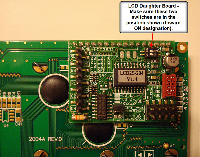
- Dip Switches
- If the LCD ribbon cable is connected properly, and power is reaching the LCD daughter board (LCD backlight is lit), check the DIP switches on the LCD daughter board. They should be set as shown below.
-
SPI Bus Check:
If the above checks are OK, this indicates that a board problem exists that is preventing the SPI bus leads from propagating to or from the processor. First check that the correct IC, 74HCT08, is properly inserted in the U9 IC socket (next to the J-LCD ribbon cable connector) on the right front of the Controller board. If that checks out, proceed below.
The leads that are involved are the SPI-OUT, SPI-IN, and SPI-CLK leads, as well as the buffered signals derived to and from these leads (see schematic). Check that pulses are appearing on the SPI-OUT and SPI-CLK leads at the PIC daughter board as well as the buffered leads. Also determine if pulses are present at the SPI-IN lead at the at the PIC daughter board. If you find a problem with these leads, examine the related traces including the derived buffer signals for bad solder connections or solder bridges. Also examine the IC that buffers these signals. -
Q:
The meter is not operating properly.
1. First, check for any red, yellow, or flashing LEDs on the front panel switches. This will alert you to any "non-standard" operating conditions - for example, an alarm trip condition, the Demo mode being activated, or a virtual coupler (instead of a real coupler) being selected. If this is not what you intended, disable or remove the "non-standard" condition using the appropriate front panel switches.
2. Make sure the intended (real) coupler is selected (by activating the coupler menu). Verify that the RCA cables from that coupler to the control head are connected properly.
3. Check the display device(s) to make sure the desired measurement is selected for display.
4. Finally, if you have established a startup set that you have used successfully in the past, activate that startup set with either a medium press of the BACKUP button, or by power cycling the meter. This gives you a quick and easy way to restore your normal settings (which you have reliably used in the past) without having to check each setting individually. -
Q:
While calibrating a coupler, when I try to save a
calibration point, I get error message "NO INPUT, VAL
IGNORED".
If you are sure that power is being applied to the coupler, and that the coupler output is connected to the correct RCA jacks, this can be caused by either the coupler trim pot being set to too low a sensitivity (toward the (CCW) position), or by a coupler with a very low sensitivity. If the trim pot is adjusted properly, and this is happening only at the very low calibration points (e.g., .05 watts, .1 watt, ...), the coupler output at these levels may be too low for reliable calibration. In this case, proceed to higher calibration points (e.g. .2 watts) until the calibration point is accepted without the "NO INPUT, VAL IGNORED" error message. In a situation like this where the coupler has low sensitivity, your low power accuracy will be limited when the power is below the lowest calibration point (.2 watts in the above example). - Q: The Bar Graph on the LCD is not displaying anything?
- Bring up the Bar Graph menu on the LCD. Make sure that the LCD is selected (BGINT, or BGBTH in the first field) and that the mode, in the second field is not set to OFF". Make sure that a signal is present, and that the Bar Graph full scale range is not set to a value too large for the signal being measured.
- Q: The Bar Graph on the LCD is displaying block characters instead of the vertical line segments.
- You must initialize the software (a one time operation) to preload the LCD module with
a special character set that the software uses to draw the vertical Bar
Graph segments. There is a power up sequence to do this - Hold in M1 and M2
while powering up the unit. You will see an initialization message.
The LCD Bar Graph should now display properly.
Note that this operation also preloads the coupler tables with the factory defaults, thereby erasing any custom calibration tables you may have created. However, you only need to perform this initialization step once after the meter is assembled, so this should not be a problem. -
Q:
Some of the 7-Segment modules do not always update at
the same rate.
The speed menu controls the nominal update rates for the various display devices including the 7-segment modules. However, you may sometimes see the update rate temporarily increase above its nominal value for one or more of the measurement types. This is by design. For example, when going from a “no power” condition to a “power on“ condition, whenever a new peak value is detected, or whenever a new SWR value is acquired, the display associated with that measurement will be updated immediately (the next display cycle) instead of waiting for the next scheduled update display cycle. This provides a real time response for these types of readings even when the display update rate is set to a low value. -
- Q: The Characters on the External 7-Segment Hi-Visibility Module are not displaying Properly.
For seven segment display modules 5 and 6 (as referenced by the Seven Segment Menu), you must identify the external type module you have connected as a TYPE A, B, C, or D module in the 7-Segment Menu. The different size 7-segment modules use different drivers, which are selected by identifying the type of the module being used as described below.
The 1.5 inch SURE modules are TYPE A modules. All of the larger size SURE modules, with the exception of the 7 inch 7-segment modules are TYPE B modules. The 7 inch 7-segment modules will work with the type set to "C' or 'D'. Use the 'D' setting for the 7 inch modules if you notice flickering with the 'C' setting. See the User Manual for additional details.
Additionally, if you are trying to drive two external 7-segment modules (instead of one external 7-segment module and the external Bar Graph module, which is the default setting), make sure that you have configured MB-1 for operation with "two external 7-segment modules" using the appropriate power up sequence described in the User Manual (Press Menu button 4 (M4) while powering up the meter.- Q: What causes the Panel Meter or Bar Graph to turn off?
Certain measurements, such as SWR, are not valid for all coupler types. For example an RF Ammeter Coupler or Generic Meter application do not support SWR measurements. If you switched from a "Power" coupler to a "non Power" coupler, and if the Bar Graph or Panel Meter was previously displaying a parameter that is no longer valid for the current coupler type, the software will turn the Bar Graph or Panel Meter OFF. If you later switch back to a Power Coupler, that device will continue to stay off unless you explicitly turn it back on. Simply turn it back on using the appropriate menu. Or an easier approach - If your startup settings meet your current needs, simply apply a medium press to BACKUP button on the front panel, or power cycle the meter. This will restore the startup configuration set.- Q: I am trying to calibrate a Crossneedle Panel Meter on Port 5, but I do not see the CROSSNEEDLE Scale Option.
Crossneedle Panel Meters occupy two D-to-A ports since two independent meter coils need to be driven. The software constrains Crossneedle Meters to the odd Panel Meter port numbers (1, 3 or 5). For example, if you calibrate a Crossneedle meter on port 5, the software uses both ports 5 and 6 to drive the single crossneedle meter identified as Meter 5.
For this reason, you will never see the Crossneedle option offered when calibrating an even number Panel Meter. In addition, since a Crossneedle meter requires two ports, the Crossneedle Scale option will not be offered in the scale type selection menu if the companion port (the next higher port number) is already in use (marked as calibrated). Since you have picked a port number that is legal for crossneedle operation (port 5), this means that you have previously calibrated port 6 and it is marked "in use" when the software determines whether it can offer you the Crossneedle Scale option. Either erase Panel Meter 6 (which will mark it as not in use), allowing you to then calibrate port 5 as a crossneedle meter, or assign the crossneedle meter to another odd port whose companion port is not in use (i.e., port 3 assuming that port 4 is not in use).- Q: I am trying to calibrate an external analog meter, but I cannot bring the needle into range even with the min CCW trim pot setting.
You have a panel meter with a full scale value less than 50 uA (the minimum limit that can be reached with MB-1's 5 volt power and the 100K trim pot). (It is probably a 30 uA meter movement.) Therefore, your meter is reading off scale even for the min (CCW) setting of the panel meter trim pot.
You can use this meter with no problem. Just adjust the trim pot to its minimum (CCW) setting (as you did) and then proceed with the calibration. The 12 bit D-to-A chip will be able to provide more than adequate resolution for an accurate calibration.- Q: I am trying to calibrate an external analog meter, but I can barely advance the needle even with the trim pot at its max (CW) position.
It is likely that you have a panel meter that has a resistor in series with the meter movement (common for voltmeter type meters) or a resistor in parallel with the meter movement (common for ammeter type meters), and is therefore not meeting the MB-1 requirements of a full scale value of 1 mA or less.
Temporarily connect the meter terminals to the 1 mA rear panel source (which is accessed by using one of the FR-POT RCA jacks on the rear of the meter and setting the front panel pot to its maximum CW position). For a 1 mA FS meter, this should drive the meter needle to approximately its full scale reading. If you are seeing much lower needle movement, the likelihood of an internal series or parallel resistor is high. Take the meter apart and remove (short) any series resistor, or remove (open) any parallel resistor. Reconnect the meter to the 50 uA source first and then work your way up to the larger current sources if required. If the needle displacement now looks reasonable based on the current source you are using, you are in business. Details for evaluating analog meters are given here. -
Q: Why am I getting an error message when I push one of the front
panel buttons?
If you push a menu button that is not valid for the current menu, or otherwise try to perform an operation that is not valid for the current configuration, one of the two error messages: “INVALID BUTTON” or “INVALID OPERATION” will be displayed on the LCD. For example, pushing menu button 4 (M4) for a menu that has only three menu items will generate the “INVALID BUTTON” error message. As another example, trying to bring up the BAND menu when the currently selected coupler port is an RF Ammeter coupler or Generic Meter Application will result in an “INVALID OPERATION” message since the Band correction functions apply to power couplers only.
Error messages specific to each menu function are covered in the relevant menu descriptions in section 3 in the User's Manual.
-
Q:
Forward Power is always reading 0.
Make sure that the meter is not in the Reflected Channel Calibration mode (indicated by an flashing yellow LED on menu button M2). If the LED is flashing, apply a long push to M2 to turn the Reflected Channel calibration mode off. -
Q:
My meter sometimes displays low power values with no transmit
power being applied.
You have a coupler that is not sensitive enough to generate an adequate DC voltage at very low power levels. When you calibrated the coupler at these low power levels (e.g., .05 watts), the ADC value for the corresponding power level, while non-zero, is operating in the vicinity of the A-to-D noise floor for that power level, and therefore some nonzero measurements may be displayed when no transmit power is being applied. When such calibration points exist, even small induced voltages on the antenna can cause these readings. -
Q:
I am applying a signal on coupler port 1, but I am seeing
measurements displayed when I select other coupler ports that
are not connected.
The corresponding coupler trim pot adjustment for your coupler (coupler 1 in your case) is set too high causing that signal on that coupler port to overdrive the corresponding input lead of the Multiplexer/Amplifier chip (MCP-6S28). The input leads of this device have a maximum rated voltage range of -0.3 volts to 5.3 volts when powered from 5 volts. If you overdrive any of the eight input leads of this device beyond the rated limit of 5.3 volts, that signal will be coupled to the output of the multiplexer even though the software is not selecting that input lead. -
Q:
If I place my transceiver into transmit, and sweep the frequency
dial across the full 500 kHz spectrum of one of the Amateur bands, I
see several frequencies within the 500 kHz range where the analog
meter seems to momentarily drop out. Is this a bug?.
This is not a bug. When I first saw this, it surprised me as well. (At the time, I had two of the other popular meters inserted in series with the MB-1 and neither one picked this up, convincing me, initially, that this was a software bug.)
Here is the explanation. When tuning across a band on some modern transceivers, the VFO implementation is such that some switching takes place at discrete frequency points. As you "roll through" these frequency points and the switching takes place, you will see a momentary signal loss of a couple of milliseconds if the transceiver is transmitting, or you will sometimes hear a click at these frequencies if the transceiver is receiving. Because the MB-1 has a very high update rate and measures instantaneous power, MB-1 will capture these short dropouts and you will see their effect on any of MB-1's fast acting display devices such as the analog meter or bar graph. The Min/Max feature will also pick up these "hits" if you configure the Min/Max feature to monitor TUNE (instantaneous) power. -
Q:
The linearity of the front panel pot seems to have changed. The step
size at the high end (max CW) of the pot travel seems to be smaller
than I recall.
You have connected a low resistance load to one or both of the RCA jacks labeled FR POT on the rear of the meter. These jacks are designed to provide a high impedance variable voltage source of approximately 0 - 5 volts for prototyping or test purposes. This voltage is controlled by the front panel pot.
The wiper of this pot feeds these RCA outputs through a 5.1K resistor. It also feeds an A-to-D channel on the controller, which is read by the software during calibration and parameter adjustment functions. The low resistance load from the RCA jack is therefore affecting linearity as seen by the A-to-D channel on the controller.
Even with a dead short on the FR POT RCA jack outputs, you should be able to obtain the full range of meter control and calibration functions using the front panel pot, although the step size will be smaller at the high end of the potentiometer's travel. It is therefore suggested that these FR POT utility outputs on the rear of the meter be disconnected during normal operation to avoid this problem. -
Q: I am trying to program the simulation values for one of
the virtual couplers (coupler 5) using the Coupler Setup. I
have the coupler menu displayed on line 4 of the LCD, but when I
enter Setup,
I am only able to choose the real coupler numbers (1 -
4).
The coupler setup (calibration) function applies to the real couplers only (1-4). To program the simulated full scale power and SWR values for any of the virtual couplers (5-8), select the DEMO menu instead on line 4 of the LCD. Then press the Set-Up button. (i.e., the virtual couplers are a subset of the Simulator, and therefore associated with the Demo (simulator) menu, not the Coupler menu). -
Q:
I
plugged an external analog meter into a rear panel RCA jack
on MB-1, and the meter
needle now looks like a pretzel.
You inadvertently plugged the meter movement into one of the two 5 volt auxiliary power RCA jacks. These are the only RCA output jacks that are capable of damaging a meter movement to that extent. It is recommended that you place two blank RCA plugs into the 5 volt auxiliary RCA power jacks to prevent this from happening again. Remove them only when you need to access the 5 volt auxiliary power source. (Two blank RCA plugs are included with the Expansion Kit.)
Use the DISPLAY function for the coupler in question
to examine the ADC values associated with the very low power
calibration points. If these numbers are very small (<10), your
coupler is not generating enough voltage for reliable operation
at these low power levels. The solution is to edit the coupler
and simply DELETE these low power calibration points.
Power levels with associated ADC values greater than 20 should
not encounter this problem. Just for comparison, the MB-HF1
coupler is a fairly sensitive coupler and generates an ADC value
of approximately 150 at the lowest power calibration point (.05
watts) when calibrated for a full scale value of 1000 watts. The "Interfacing
your own Couplers" page has some guidelines that will
help you understand the restrictions when using your own
couplers with MB-1.
Since the maximum output of the 15 bit input chain is 32,767, if you follow the calibration procedure of adjusting the coupler trim pot to achieve an ADC output of approximately 30,000 when the input device is generating its maximum full scale voltage, you will not have this problem. The maximum ADC output occurs when the coupler port input signal (after being reduced by the voltage divider formed by the 100K input resistor and the setting of the 200K coupler trim pot) is exactly 4.096 volts at the input lead of the MCP-6S28. (4.096 volts is the voltage generated by the MCP-1541 voltage reference chip and used by PIC ADC converter to define its full scale output.) Therefore, setting the ADC count to 30,000 with the coupler trim pot when the maximum DC voltage from the input is being applied to the coupler port guarantees that the corresponding signal on the multiplexer input lead will always be less than 4.096 volts.
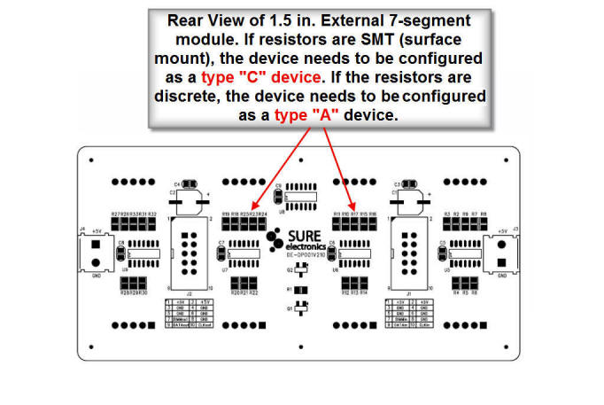
SURE Electronics, who makes the external 7-segment display modules, has two different designs for the 1.5 inch 7-segment modules that MeterBuilder provides with the Expansion Kit, both of which will work with MB-1. MB-1 is shipped with a default setting for a type "A" device. However, some of the SURE 1.5 inch external 7 segment displays are type "C" devices, which require a different setting.
To determine if the type of external 7-segment module, look at the rear of the 7-segment module. If it has surface mount resistors (see below) it must be configured as a type C device. If it has discrete resistors, the default setting of type "A" is correct and does not need to be modified.
Steps for Changing the Default setting for the external 7-segment display for type C for 1.5 inch 7-segment Display Modules
- Turn the meter on. Select the Digital (Seven Segment)
Display menu by tapping the the second button from the left
on the bottom row of buttons.
- With the 7-segment display menu selected on line 4,
select module D5 on the menu line by tapping M1 (menu button
1) repeatedly until D5 is displayed. This selects the first
external display module. You will see that the fourth field
in the line 4 menu is set "A" (type A device). This should
be changed to "C" (type C device). Do this by tapping M4
(menu button 4) repeatedly until the value in the fourth
field changes to "C".
- To save these settings so that they are automatically restored the next time you power up the meter, apply a long press to M1 (menu button 1). You will receive a confirmation message that settings have been saved.
If you plan to use two 7-segment external displays with MB-1, simply repeat the above procedure for module D6 (the second external display) after configuring the meter for two external 7-segment displays. See the User Manual for details on configuring MB-1 to work with two external 7-segment display modules.