| As with all Set-Up functions,
first display the applicable menu on line 4 of the LCD (the Panel Meter Menu in
this case). Then press the
Set-Up button (Top Right Button - Long press). |
 |
|
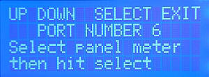
| Select the Panel Meter number:
The software will enter the Panel Meter calibration setup routine
bringing up the screen to the right. Press the UP or DOWN buttons
(M1 or M2) to select the Panel Meter you want to
calibrate. Then press SELECT (M3).
Make sure you use the UP/DOWN "buttons"
represented by the first two menus choices on the top line of the
LCD using the M1 and M2 menu buttons, and not the buttons with
the Up-Scroll and Down-Scroll silkscreen labeling.
Crossneedle Panel meters require two panel meter ports (and
therefore occupy two panel meter numbers). Crossneedle meters can
only be set up as Panel Meters 1, 3 or 5.
Panel meter ports 1 and 2 are connected to the internal
crossneedle meter provided with MB-1. Therefore, use any of the other four panel meter ports
(3 - 6). Port 6 is chosen for this example. |
 |
|
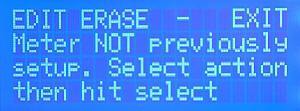
| Select Operation: If the
Panel Meter port that you selected is already calibrated, that fact will
be announced on this screen. If the port is already calibrated and you want to
modify some of the settings, press EDIT (Menu Button 1 - M1).
If you want to perform a new calibration as we do here, and if the panel meter
port was currently in use, you would press the ERASE button (M2)
to erase the old settings.
In this example, the selected panel meter was not previously
calibrated. Therefore, press the EDIT button (M1)
to start a new calibration. |
 |
|
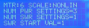
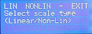
| Select Scale Type: Select the Scale Type. In this case
we select the Nonlinear Scale, which corresponds to menu
choice M2, since NONLIN
is the second item in on the LCD menu on the top line.
For this example, we
are calibrating Panel Meter port 6, and therefore the Crossneedle
selection is not applicable (and therefore not made available for
selection).
(Remember that Crossneedle meters can only occupy odd number
ports 1, 3 or 5.)
|
 |
|
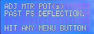
| Adjust Trim Pot: When this
screen is displayed, the full scale output of the D-to-A chip is
applied to the panel meter RCA jack (or two RCA jacks in the case of
a crossneedle meter). This screen prompts you to adjust the
panel meter's trim adjustment pot so that the needle deflects beyond its
full scale reading, but not excessively. Adjust the pot until the needle contacts the
needle stop (and then just a bit more). This will give you the extra
drive needed if you want to use the Soft Overrange feature below.
After adjusting the trim pot(s), press any of the four Menu buttons M1
- M4.
This will remove the full scale drive from
the panel meter returning the needle to its resting position. |
 |
 |
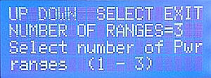
| Select Number of Power Scales:
All Panel Meter calibrations require at least one power range. For the
Nonlinear case,
you may select from one to three ranges.
For nonlinear meter calibrations, if you select more than one range, the
full scale value of the second (and third) range will be x10 (and
x100) the value of the first range. This rule is built into the
software. |
 |
|
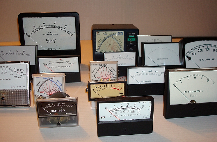
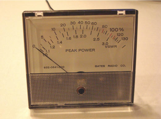
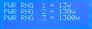
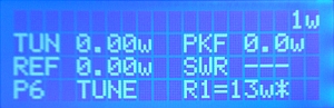
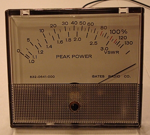
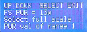
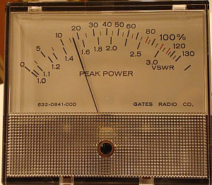
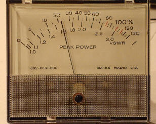
Select FS Value of First (Lowest) Power
Scale:
The meter we are using has a full scale power value of 130
watts. We will therefore select the FS value of the first range to
be 13 watts. This will give us three power scales: 13w, 130w (13 x
10), and 1300w (13 x 100).
With the meter being used in this example, this will require the user to divide by 10 when interpreting
measurements on the lowest range, and multiplying by 10 when
interpreting measurements on the highest range.(We could have set the full scale range of the first range to
130, which would have given us scales of 130, 1300, and 13,000.
However, the
choice above is a better selection for Amateur Radio
use.) |
 |
|
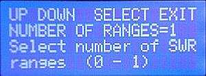
| Select Number of SWR Scales:
This screen is used to specify the number of SWR scales. Enter 0 if you want to use
the meter for power measurements only (no SWR scale). Select 1 if you want to
define an SWR scale as well. |
 |
|
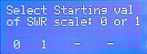
| Select Starting Val (0 or 1) of SWR
Scale: If you will be setting up an SWR scale as determined in
the above step, the screen to the right is displayed. Here, you define the starting value
of the SWR scale as 0 or 1. All "real" SWR scales start at 1, but if you have a meter scale that starts at 0
(a common case on many non-Amateur Radio meters), and if you want to use that
meter
to display SWR measurements,
select the value 0 in this step. The software will then idle the
needle at a reading of 1 - a bit unconventional, but without this
capability, you would not be able to use 0-based scales at all for
displaying SWR measurements.
In this example, we are using an actual SWR scale. Since 1 is the second choice on the menu line, we select it with
menu button 2 (M2). |
 |
|
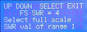
| Select FS Value of SWR Scale:
The meter we are using has a full scale SWR value of 3.0. As
discussed above, since the scale has some additional room, we set the FS
value of the SWR scale to 4.0 and eyeball the calibration points between
3 and 4 during calibration.
Alternatively, temporarily
place a piece of masking tape on the meter case with spaced
tick marks between 3 and 4. |
 |
|
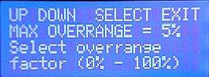
| Select Soft Overrange Value:
The screen to the right allows you to specify a
soft overrange value
- a percentage beyond full scale that defines the maximum travel of
the needle when an overrange condition occurs. This allows you to observe
an overrange condition on the analog meter without risking damage
to the meter movement. |
 |
|
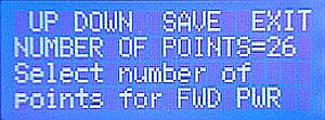
| Select Number of Cal Points for Power Scale:
Use this screen to specify the number of calibration points for
the power scale. With our 13 watt (lowest scale) full scale value, a
choice of 26 points will give us good
resolution (e.g., .5w, 1.0w. 1.5w, ...) and convenient tick marks.
|
 |
|
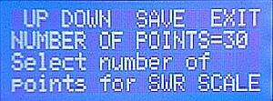
| Select Number of Cal Points for SWR Scale:
Use this screen to specify the number of calibration points for
the SWR scale. If we choose 30 points, this will also give us good
resolution (e.g., 1.1, 1.2, 1.3, ... 4.0), again at convenient tick marks.
|
 |
|
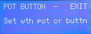
| Select pot or buttons to Adjust
needles: This screen allows you to either use the front panel
pot to adjust the meter needle during calibration, or the "UP" "DOWN" buttons
corresponding to Menu Buttons 1 and 2 respectively. The pot is easier in most
cases although the buttons give you slightly finer control. We
use the Pot for the remainder of this example |
 |
|
| Announce Start of Power calibration:
After the "POT" choice is made in this example, this screen simply announces that the software is ready to start the
Power Calibration sequence. Hit any of the four menu buttons, M1 -
M4 to
proceed.
|
 |
|
| Actual Power
Scale Calibration: The actual power calibration now
begins. The screen prompts you at each of the 26 power calibration
points. The screen to the right shows the third power calibration point
(.5,
1.0, 1.5). For each point, advance the needle,
using the front panel pot, to the corresponding
location on the meter scale. Then press the SAV button (M3).
(Remember that we have defined our low scale at 13, not 130.)
Even if you selected the pot to adjust the needle during calibration, you can press the
TRIM button (Menu
button M1) after doing an initial adjustment with the pot
(but before pressing the SAVE button). This provides a "nudge" function, giving you very fine
control using the UP/DOWN buttons for positioning the needle.
This will not be necessary
with most meters.
Convention: All menu choices that
perform a single function (like TRIM, skip (SKP), and
exit (EXT)
in the menu to the right) are requested with a short push of the
corresponding menu buttons (M1, M2, and M4).
Since there are only four menu buttons (M1 - M4), those menus that have five
choices like the one shown to the right on line 1 of the LCD are handled as follows.
For this menu, the third menu item SAV/PRV controls both the
SAVe function and the PRV (previous) function (backs up
to the previous calibration point). For
these dual menu cases, you select the first function (SAV) with a
short press of the corresponding menu button (M3 in this case).
You select the second function (PRV) with a long press of the
corresponding menu button (M3).
|
 |
 |
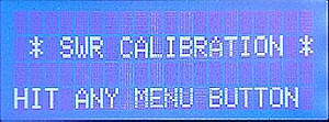
| Announce Start of SWR calibration:
After all 26 power points have been calibrated, this screen is displayed. This
screen simply announces that the software is ready to enter the SWR
Calibration sequence. Hit any of the four menu buttons to proceed.
|
 |
|
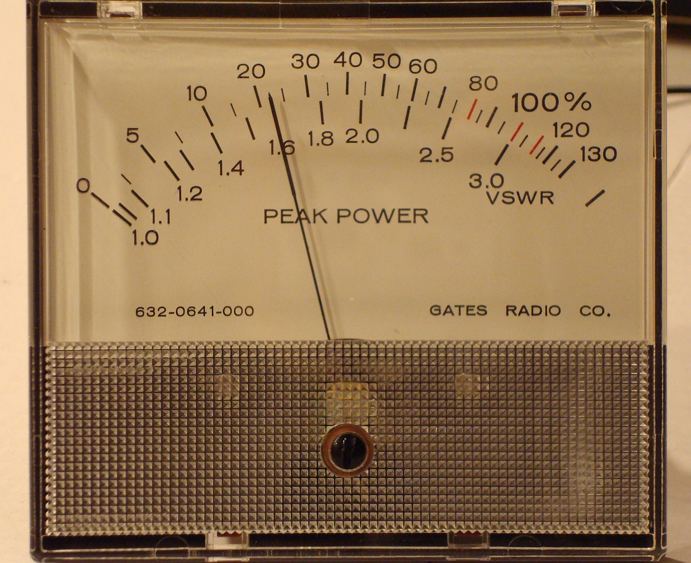
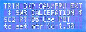
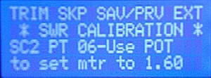
| Actual SWR
Scale Calibration: The actual SWR calibration now
begins. The screen prompts you at each of the 30 SWR calibration
points (1.1, 1.2, 1.3, 1.5, 1.6..., 4.0) The screen
to the right shows the sixth SWR calibration point (1.6).
For each point, advance the needle to the
corresponding location on the SWR scale using the front panel pot. Then press the SAV
button (Menu
Button 3).
As with calibration of the Power scale, the TRIM function is available
for each point by
pressing M1 (TRIM) if
you want to use the "nudge" function.
|
 |
 |
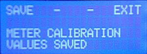
| Save Settings to EEProm: After
you have saved the setting for the last calibration point, you are given the option
to save the Panel Meter calibration settings to EEProm by pressing SAVE (M1). |
 |
|
| Confirmation: The screen on
the right confirms that the calibration values have been save to EEProm. |
 |
|
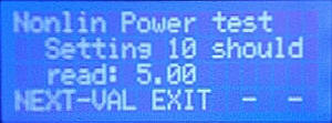
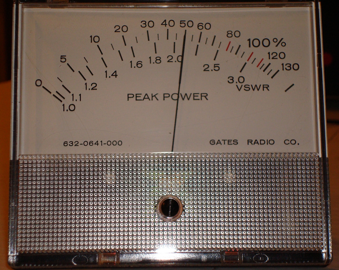
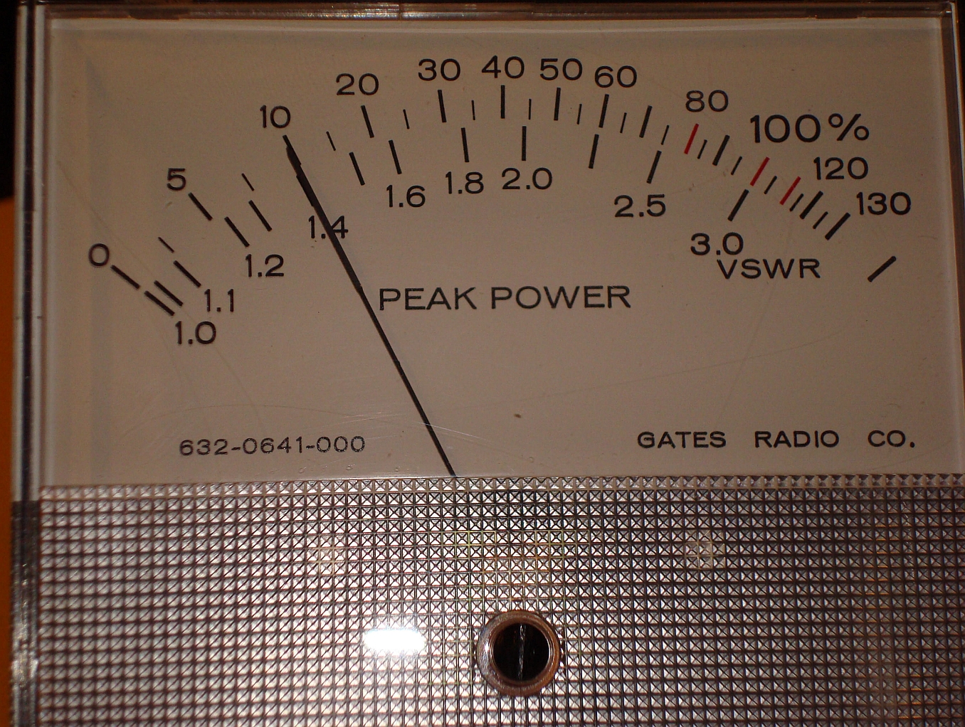
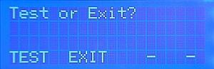
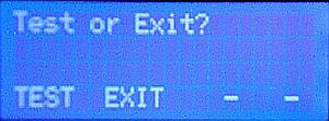
| TEST or EXIT option: The
software now gives you the option to EXIT (Menu button M2)
resuming normal meter operation, or to TEST the calibration
(Menu button M1). We choose
TEST in this example. The results are shown in the table
below. |
 |
|
 Index
Index